

How To Access Accelerometer Registers Adxl345
ADXL345
The ADXL345 is a three centrality accelerometer and there are two basic uses for this device:
- Orientation: Determine which way is up using gravity.
- Instantaneous forcefulness: Detect applied forces.
Typical applications include tilt and motion sensing eastward.grand. self levelling platforms, drone orientation, angle of tilt measurement, drop sensing.
It can measure accelerations up to 16g with 13bit resolution translating to a resolution of iii.9mg (grand representing gravity at 9.8m/southwardii).

To make it more useful, it has several congenital in functions:
- Thresholds.
- Tapping.
- Falling.
- Cocky test.
You tin can setup thresholds on each centrality to permit detection of move i.e. above a certain acceleration level it will generate an interrupt. You could use that for detecting if the contents of a box of sensitive equipment had been mishandled.
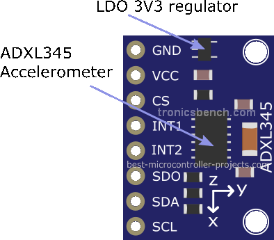
ADXL345 Breakout board

You lot tin can also observe unmarried or double taping in any direction. Some other built in function tin can notice costless fall for drop sensing.
ADXL345 Specification
| Parameter | Value |
|---|---|
| Voltage Supply (Vs) | 2V0 ~ 3V6 |
| Digital Supply voltage (Vdd i/o) | 1.7V ~ Vs |
| Interface | I2C / SPI |
| I2C Address (depends on ALT ADDR) | 0x1D, 0x53 |
| Interface Speed | 100kHz, 400kHz / 5MHz |
| Resolution (2g to 16g) | x ~ 13 bits |
| Noise in LSB (400Hz, 2V5) [1] [2] | <ane.7LSB (typ) |
| Shock survival | 10,000g |
| Active electric current (ODR >=100Hz) | ~150uA (170uA max) |
| Active current (ODR <100Hz) | ~30uA |
| Standby mode (leakage current) | 0.1uA |
| Operating temperature | -40°C ~ 85°C |
[1] - Racket performance improves with college supply voltage.
[two] - Datasheet figure 51.
ADXL345 Block Diagram
 From Analog devices ADXL345 datasheet.
Breakout board Specification
Every bit above except for the power supply. The breakout lath has a LDO 3V3 regulator so the input voltage to VCC must be:
4.0V to 6V.
Note: This is but for the breakout board - the actual scrap Vsmin = 2V0.
Besides:
- CS is pulled loftier by a 10k resistor (active). Can exist 4k7 on some boards.
- ADDR(SDO) is pulled depression by a 4k7 resistor.
- SCL is pulled high to 3V3 past a 4k7 resistor.
- SDA is pulled loftier to 3V3 past a 4k7 resistor.
- VDDIO is connected to VS and both connect to 3V3.
Since the I2C interface uses open up drain outputs, the interface is compatible with a 5V system. This is true as the Arduino never drives out 5V it merely tristates an output to let the voltage level pull to 3V3. To generate a zero it outputs a digital zero which is besides compatible with the 3V3 interface.
Warning: If you employ the fleck in SPI fashion so you volition demand level translators (when using a 5V controller) or a controller lath that only uses 3V3 throughout.
Breakout Lath ICs
Note: Note: The add-on of a 3V3 regulator ways the board can be used in a 5V system if I2C mode is used.
ADXL345 Breakout board GY-291 Schematic

ADXL345 Interface to Arduino
Using the ADXL345 with the Arduino is quite like shooting fish in a barrel if you utilize the I2C interface, equally this allows to controller to operate at 5V and the ADXL345 to operate at 3V3.
Note: In I2C fashion the SDO pivot is an input, selecting an address.
I2C Address
For I2C mode operation the chip has an address pin. On the breakout board this is pulled low giving an I2C address of:
| State of ADDR/SDO pin | I2C Address (hex) | I2C Address (binary) |
|---|---|---|
| ADDR pulled high | 0x1D | %0001-1101 |
| ADDR pulled low | 0x53 | %0101-0011 |
Note: The ALT ADDRESS pin is an output in SPI mode, for SDO.
ADXL345 Output Data Rate
The ODR is 100Hz set by $.25 in the BW_RATE register. In the library employ setRate() and the following divers values:
ADXL345_RATE_3200 // Must use SPI way ADXL345_RATE_1600 // Must utilize SPI mode ADXL345_RATE_800 // Must use I2C charge per unit of >=400kHz ADXL345_RATE_400 // Must use I2C rate of >=200kHz ADXL345_RATE_200 // Must use I2C rate of >=100kHz ADXL345_RATE_100 (default) ADXL345_RATE_50 ADXL345_RATE_25 ADXL345_RATE_12P5 ADXL345_RATE_6P25 ADXL345_RATE_3P13 ADXL345_RATE_1P56 ADXL345_RATE_0P78 ADXL345_RATE_0P39 ADXL345_RATE_0P20
Irresolute the data rate is useful for power saving (past going wearisome).
At 100Hz and above the electric current consumption is 140uA (p14 of datasheet) - except for 1600Hz (90uA). The minimum y'all can get is at 0.39Hz (and below) with 23uA used.
ADXL345 Resolution
Yous tin select the acceleration range from the following values:
2g, 4g, 8g, 16g.
The aforementioned scaling cistron is used in all resolutions considering the internal DAC resolution changes from 10bits to 13 bits every bit each resolution is selected. And then each bit is always worth iii.9mg:
| Adding g/LSB | Result |
| 2/pow(2,ten-ane) | 0.003906 |
| 4/prisoner of war(2,xi-i) | 0.003906 |
| 8/pow(2,12-1) | 0.003906 |
| 16/pow(2,13-1) | 0.003906 |
Note the '-1' allows for the sign bit to give positive or negative results.
Using 16g mode gives maximum dynamic range.
However an excerpt from the datasheet shows the actual deviation from the above ideal values (Sensitivity deviation from ideal):

If you restrict the range of the adxl345 to 10bits so information technology becomes less sensitive (fairly obvious). For full range you lot go the typical sensitivity of 3.9mg/LSB and 3.5 ~ iv.3mg/LSB min ~ max deviation (this is set using the FULL_RES bit). Why you lot would restrict to 10bits is something I don't sympathize - seems pointless.
Why not ±90°?
Why can't the ADXL345 accelerometer indicate ±90°?
If you lot run the program beneath you will see that the accelerometer is extremely good at indicating tilt at low angles (on a flat surface) to well-nigh seventy°, but does not reach ±ninety°. In fact it can't seem to accomplish that magic number ±xc°!
At first, I idea at that place was something wrong with the accelerometer since no one seems to talk about this. Why should information technology non be possible to measure all angles?
If you call up about property a slice of woods - the maximum force on information technology is when yous concur it horizontally. The more you betoken it upwards, to the vertical position, the less gravity tin bear on it, hence - the accelerometer becomes less sensitive.
So it turns out that the sensitivity of the accelerometer decreases with increasing angle and follows a nigh sinusoidal response, and accuracy decreases the closer you get to ±ninety° of tilt.
"The sensor is a polysilicon surface-micromachined structure built on pinnacle of a silicon wafer. Polysilicon springs suspend the structure over the surface of the wafer and provide a resistance against forces due to applied acceleration." [datasheet]
Y'all tin imagine the sensor every bit a beam suspended on springs, with the capacitance between the beam and the support base giving the acceleration measurement. When the beam is perpendicular to the dispatch field small tilt changes volition have a big effect as gravity acts over a larger area.
As the beam tilts vertically, the sensor becomes less sensitive (interacting with the gravity vector less) until, at total vertical orientation, information technology tin not return a reading since the gravity vector has no event on the beam.
There is a very practiced word of accelerometer sensitivity in Analogue Devices Application note AN-1057 by C Fisher here. The post-obit diagram is from that awarding note:

The diagram shows that around 0° ~ 23° tilt yous only demand a sensitivity of 16mg/LSB to resolve ane° steps, and effectually 60° tilt you need 8mg, and around 80° you need 4mg. This is why the ADXl345 can not brandish 90° every bit its sensitivity is too coarse to resolve tilt at that angle (iii.8mg). So the ADXL345 is good for tilt up to about ±eighty°. This is for the case where you want to resolve tilt measurement to within ane°.
TIP: Increase resolution by oversampling to resolve smaller angles.
Why tin't I measure yaw?
Yaw is the rotation about the z axis - or compass heading. You may think that the ADXL345 z axis is non working only it is!
When you rotate the accelerometer about the 10 or y axis, sensors experience more or less of the gravity vector and therefore output different values of acceleration.
When you rotate the accelerometer well-nigh the z axis the sensor experiences the same value of gravity vector then you can't measure yaw.
This is why accelerometers are used in conjunction with a gyroscope or magnetometer for measuring yaw values.
What is the z accelerometer useful for?
So so the question becomes why do you demand a z-accelerometer measurement?
The z axis accelerometer indicates deviation from vertical. In conjunction with either ten or y accelerometer values yous can calculate pitch and roll (deviation from vertical in the x or y directions).
ADXL345 Datasheet
Download here.
Hardware Connections:
You can apply an Arduino Uno or Nano (the Nano is convenient for solderless breadboard utilise every bit it fits into one quite nicely). Hither the ADXL345 is used on the Arduino in I2C fashion so just connect SDA, SCL, power and ground:
| Arduino Uno/Nano Connection | ADXL345 Connectedness |
| A4 | SDA |
| A5 | SCL |
| GND | GND |
| 5V | Vcc |
ADXL345 interfacing with the Arduino is simply to connecting the I2C interface equally above.
Software
I2Cdev library
The I2Cdevlib has ADXL345 library code as well as lawmaking for many other devices.
https://github.com/jrowberg/i2cdevlib
This library has a lot of features, supported fries, and can operate on multiple processors but information technology is a little more involved to install and you lot tin can not employ the automatic Arduino cypher file installer.
Unzip the file (ic2devlib-principal) then navigate to the Arduino directory within ic2devlib-chief. Copy the directories ADXL345 and I2Cdev to the Arduino libraries directory, usually constitute hither (on windows):
C:\Users\<User name>\Documents\Arduino\libraries
ADXL345 Self Test Sketch
Because the device is a mechanical system the ADXL345 includes a cocky test circuit that imposes an electrostatic field on the concrete measuring elements. These has a similar effect to gravitational acceleration adding to the existing acceleration element.
Notation: Datasheet page 31 has more on using the self-exam.
The following program tests the scrap at 3.3V (the supply voltage changes the exam parameters). The program volition output the results to the serial monitor and gives yous a PASS/FAIL indication. Yous can as well notice raw g values, coil and pitch.
Use this sketch if you affair that the AXL345 is non working.
// By John Chief © all-time-microcontroller-projects.com // ADXL345 Self Test, show g and scroll pitch values #include "math.h" #include "Wire.h" #include "I2Cdev.h" // Has MIT license. #include "ADXL345.h" ADXL345 accel ; #ascertain LED_PIN LED_BUILTIN // (Arduino is thirteen, Teensy is 6, nano? so utilize LED_BUILTIN) bool toggleLED = false ; static byte showAngles = 0 ; // Brandish operation void setup () { Wire . begin (); Serial . begin ( 115200 ); // initialize device Series . println ( F ( "Starting I2C devices..." ) ); accel . initialize (); Serial . println ( F ( "Checking ADXL345..." ) ); if ( accel . testConnection ()) Serial . println ( F ( "ADXL345 comms Ok." ) ); else { Serial . println ( F ( "ADXL345 comms failed." ) ); while ( 1 ); // Hang on error. } Serial . println ( F ( "Enter t - Cocky exam, s - Evidence angles" )); accel . setFullResolution ( i ); // 0 => x bit manner. accel . setRate ( ADXL345_RATE_100 ); // This is default but shows the value. accel . setLowPowerEnabled ( 0 ); accel . setRange ( 3 ); // 0 => 2g, three => 16g pinMode ( LED_PIN , OUTPUT ); } // Get readings for self exam - A set up of n averaged results. void ADXL345GetAvgN ( int16_t * xi , int16_t * yi , int16_t * zi , uint8_t n ) { int16_t x , y , z ; int32_t ax , ay , az ; uint8_t i ; ax = 0 ; ay = 0 ; az = 0 ; for ( i = 0 ; i < n ; i ++) { accel . getAcceleration (& x , & y , & z ); ax += x ; ay += y ; az += z ; delay ( 100 ); // Don't read faster than 100Hz: (ten*100ms=1s 1s/10=100ms) } * 11 = ax / north ; * yi = ay / n ; * zi = az / northward ; } void print_minmax ( int vmin , int vmax ) { Serial . impress ('('); Series . print ( vmin ); Series . print ( " ~ " ); Serial . print ( vmax ); Series . print (')'); } // This function setsup the relevant parameters while preserving them e.g. range void ADXL345SelfTest ( void ) { uint16_t fr , st , rt , lp , ra ; fr = accel . getFullResolution (); rt = accel . getRate (); lp = accel . getLowPowerEnabled (); ra = accel . getRange (); int16_t avg_x = 0 , avg_y = 0 , avg_z = 0 ; int16_t avg_stx = 0 , avg_sty = 0 , avg_stz = 0 ; int16_t ax , ay , az ; int16_t ten , y , z ; uint8_t i ; // Setup operating mode required for self test. accel . setFullResolution ( 0 ); // 0 => 10 bit mode. accel . setRate ( ADXL345_RATE_100 ); accel . setLowPowerEnabled ( 0 ); accel . setRange ( 3 ); // 3 => 16g ADXL345GetAvgN (& avg_x , & avg_y , & avg_z , 10 ); accel . setSelfTestEnabled ( i ); ADXL345GetAvgN (& avg_stx ,& avg_sty ,& avg_stz , v ); // Let device settle for >=4 samples. ADXL345GetAvgN (& avg_stx , & avg_sty , & avg_stz , 10 ); accel . setSelfTestEnabled ( 0 ); // Display results x = avg_stx - avg_x ; y = avg_sty - avg_y ; z = avg_stz - avg_z ; Serial . print ( "\nstx-x\t" ); Serial . print ( ten ); Series . print ( "\t" ); Series . print ( "sty-y\t" ); Serial . impress ( y ); Serial . impress ( "\t" ); Serial . print ( "stz-z\t" ); Series . print ( z ); Serial . print ( "\t" ); // 3V3 error limit scale factors. #define scale_factor_xy 1.77; #define scale_factor_z 1.47; bladder vmin , vmax ; Serial . impress ('\n'); //Value limits are from ADXL345 datasheet - Tables 14 and xviii. vmin = 6 * scale_factor_xy ; vmax = 67 * scale_factor_xy ; Serial . print ( ( x >= vmin && x < vmax ) ? "X PASS " : "X FAIL " ); print_minmax ( vmin , vmax ); Serial . print ('\north'); vmin = - 67 * scale_factor_xy ; vmax = - 6 * scale_factor_xy ; Series . impress ( ( y >= vmin && y < vmax ) ? "Y Pass " : "Y FAIL " ); print_minmax ( vmin , vmax ); Serial . print ('\northward'); vmin = x * scale_factor_z ; vmax = 110 * scale_factor_z ; Serial . impress ( ( z >= vmin && z < vmax ) ? "Z PASS " : "Z FAIL " ); print_minmax ( vmin , vmax ); Serial . print ('\n'); accel . setFullResolution ( fr ); accel . setRate ( rt ); accel . setLowPowerEnabled ( lp ); accel . setRange ( ra ); } void showAccelAngles ( void ) { float x , y , z ; int16_t ax , ay , az ; // Bear witness angles // Datasheet: OPERATION AT VOLTAGES OTHER THAN 2.5 V // 3v3 X,Y 25mg too high, z 20mg too low // 3V3 lsb value 265/g (g/265)=0.03698 // 2V5 lsb value 256/grand (g/256)=0.03828 z axis unaffected by voltage supply. #ascertain ADXL345_LSBVAL_3V3 iii.698E-3 #define ADXL345_LSBVAL_2V5 3.828E-3 accel . getAcceleration (& ax , & ay , & az ); x = ax * ADXL345_LSBVAL_3V3 - 25E-3 ; y = ay * ADXL345_LSBVAL_3V3 - 25E-3 ; z = az * ADXL345_LSBVAL_2V5 + 20e-3 ; float fNum ; Serial . impress ( F ( "g values: " )); fNum = x ; Serial . print ( fNum ); Series . print ( "\t" ); fNum = y ; Serial . print ( fNum ); Serial . impress ( "\t" ); fNum = z ; Serial . print ( fNum ); Serial . print ( "\t" ); float r = sqrt ( 10 * x + y * y + z * z ); // Angle from x,y centrality to gravity vector. int roll = 180 / M_PI * ( M_PI / ii - ( acos ( y / r ) ) ); int pitch = 180 / M_PI * ( M_PI / ii - ( acos ( x / r ) ) ); Series . print ( F ( "Roll " )); Serial . print ( gyre ); Serial . print (' '); Serial . print ( F ( "Pitch " )); Serial . print ( pitch ); Serial . print (' '); Serial . print ('\n'); } void loop () { float 10 , y , z ; static byte ch ; if ( Series . bachelor ()) { ch = Serial . read (); } if ( ch =='t') { Serial . println ( F ( "Testing..." )); ADXL345SelfTest (); showAngles = 0 ; } else if ( ch =='s') showAngles = one ; if ( showAngles ) showAccelAngles (); toggleLED = ! toggleLED ; digitalWrite ( LED_PIN , toggleLED ); filibuster ( 200 ); } [File:adxl345_self_test.ino]
Cocky Test Program Output
Type 't' to showtime a self-test and 'due south to output m, roll and pitch values.
The following shows typical output from the programme:
Starting I2C devices...
Checking ADXL345...
ADXL345 comms Ok.
Enter t - Cocky test, s - Show angles
Testing...
stx-ten 59 sty-y -18 stz-z 88
X Laissez passer (ten ~ 118)
Y Pass (-118 ~ -10)
Z Pass (xiv ~ 161)
g values: -0.17 -0.02 ane.05 Ringlet 0 Pitch -9
chiliad values: -0.21 0.00 i.08 Roll 0 Pitch -11
g values: -0.18 -0.01 ane.03 Roll 0 Pitch -9
thousand values: -0.17 -0.02 1.07 Curl -1 Pitch -9
k values: -0.17 -0.02 1.07 Coil 0 Pitch -8
g values: -0.01 -0.03 ane.00 Curlicue -1 Pitch 0
thou values: -0.69 -0.06 0.77 Roll -3 Pitch -41
1000 values: -1.thirty -0.15 0.36 Whorl -6 Pitch -73
g values: 0.24 -0.21 0.95 Roll -12 Pitch 13
m values: 0.22 -0.42 0.96 Roll -23 Pitch 11
g values: -0.06 -0.82 0.87 Roll -43 Pitch -2
1000 values: -0.01 0.05 1.01 Roll 2 Pitch 0
Sketch Example 2
This plan outputs only roll and pitch values - these are used to show a processing simulation of the orientation of the accelerometer. This is the type of view produced by the processing code for the Arduino sketch below:
// Past John Main © best-microcontroller-projects.com // This sketch outputs serial data as 2 parameters (roll and pitch) // for display in processing code on PC. #include "math.h" #include "Wire.h" #include "I2Cdev.h" #include "ADXL345.h" #ascertain LED_PIN LED_BUILTIN // Macros to allow 0 ~ 180 mapped to -xc to 90 ADXL345 accel ; bool blinkState = false ; void setup () { Wire . begin (); Serial . begin ( 115200 ); accel . initialize (); accel . setRate ( ADXL345_RATE_100 ); // This is default but shows the value. accel . setFullResolution ( 1 ); // 0 => x bit way. accel . setLowPowerEnabled ( 0 ); accel . setRange ( 0 ); // 0 => 2g, 3 => 16g pinMode ( LED_PIN , OUTPUT ); } void loop () { float r , x , y , z ; int16_t ax , ay , az ; // Datasheet: Operation AT VOLTAGES OTHER THAN ii.v 5 // 3v3 X,Y 25mg also loftier, z 20mg also low // 3V3 lsb value 265/1000 c (g/265)=0.03698 // 2V5 lsb value 256/g (g/256)=0.03828 z axis unaffected by voltage supply. #ascertain ADXL345_LSBVAL_3V3 3.698E-iii #define ADXL345_LSBVAL_2V5 3.828E-3 accel . getAcceleration (& ax , & ay , & az ); x = ax * ADXL345_LSBVAL_3V3 - 25E-iii ; y = ay * ADXL345_LSBVAL_3V3 - 25E-iii ; z = az * ADXL345_LSBVAL_2V5 + 20e-three ; r = sqrt ( x * x + y * y + z * z ); // Angle from x,y axis to gravity vector. int roll = 180 / M_PI * ( M_PI / 2 - ( acos ( y / r ) ) ); int pitch = 180 / M_PI * ( M_PI / 2 - ( acos ( x / r ) ) ); Serial . print ( scroll ); Serial . print (' '); Series . impress ( pitch ); Serial . print (' '); Serial . print ('\northward'); // blink LED to indicate action blinkState = ! blinkState ; digitalWrite ( LED_PIN , blinkState ); delay ( 50 ); } [File:degrees-roll-pitch.ino]
Processing Sketch
This shows the orientation of the accelerometer every bit a 3d paradigm on screen - it mimics the orientation of the accelerometer in existent time. Download processing here. Note: Change the Serial port to your own ane. When you run the program below the output text screen will show the available serial ports. Change COM19 to friction match yours.
// Past John Principal © best-microcontroller-projects.com // This sketch accepts series data as 2 parameters (whorl and pitch) // and displays a 3d representation of the accelerometer. import processing . serial .*; Serial myPort ; String inString ; // Input string from serial port int lf = 10 ; // ASCII linefeed bladder rx , ry , rz ; float mouseZoom ; float RAD_TO_DEGREE = 180 / PI ; float DEGREE_TO_RAD = PI / 180 ; void setup () { size ( 400 , 400 , P3D ); print ( "-----------------------------" ); print ( "Showtime" ); impress ( "--------------------\northward" ); // List all the available series ports: printArray ( Serial . listing ()); // Open the port you are using at the rate you want: // Replace COMP19 with whatsoever port you lot desire to utilise. myPort = new Serial ( this , "COM19" , 115200 ); myPort . bufferUntil ( ENTER ); mouseZoom = width / two ; } void mouseWheel ( MouseEvent event ) { float eastward = result . getCount (); mouseZoom += due east * x ; } void draw () { int x , y = 70 , ysep = twenty ; background ( 80 ); fill (# ffffff ); translate ( 100 , 180 ); if ( inString != cypher ) { inString = trim ( inString ); text ( "received: " + inString , 10 , y ); y += ysep ; //50 int [] nums = int ( split up ( inString ,' ') ); text ( "scroll " + nums [ 0 ], 10 , y ); y += ysep ; // seventy text ( "pitch " + nums [ i ], 10 , y ); y += ysep ; rx = nums [ 0 ]; ry = nums [ 1 ]; } pushMatrix (); // FOV START float fov = 0.6086836 ; float attribute = 1 ; bladder cameraZ = 636.74 ; perspective ( fov , aspect , cameraZ / 10.0 , cameraZ * 10.0 ); // END FOV // Angle photographic camera view to left and to a higher place (1st 2 params). camera (( width / 2 )* 0.four , height / 2 * 0.05 , ( height / 2 ) / tan ( PI / 6 ), width / 2 , acme / 2 , 0.5 , 0 , ane , 0 ); translate ( 200 , 200 ); stroke (# F4F52F ); // Axes box ( 170 , one , ane ); box ( ane , 1 , 60 ); stroke ( 0 ); // Axes - processing : y downward x right z out of page // Axes - accelerometer : y - into page, x right, z up. rotateX (- rx * DEGREE_TO_RAD ); rotateZ (- ry * DEGREE_TO_RAD ); // Different z axis for accelerometer. fill (#6598 C9 , 100 ); box ( 150 , 10 , xl ); make full (# F52FF2 , 100 ); translate ( 0 , 10 , 0 ); box ( 150 , ten , 40 ); popMatrix (); } void serialEvent ( Serial myPort ) { inString = myPort . readString (); } [File:roll_pitch.pde]
Deep Swoop into MEMS
This a cutting edge academy level tutorial on mems and micromachined structures with specific coverage of oscillator applications.
This provides a fascinating await at the world of micromachining from structures created between 1989 and the present day (Video released in Feb 2019). The tutorial is from 2018.
It starts off showing how structures are created using transistor etching techniques. The talk is given Professor Clark Nguyen - He was Bill Tang'due south undergraduate researcher when MEMS was being invented.
This is a groovy video to see cutting border techniques - it is very advanced but starts off slowly, describing early designs - very good to dip into.
Site Map | Terms of Use


How To Access Accelerometer Registers Adxl345,
Source: https://www.best-microcontroller-projects.com/adxl345.html
Posted by: cephaswhersely1982.blogspot.com
0 Response to "How To Access Accelerometer Registers Adxl345"
Post a Comment